3D Printer
Terminology
Created on April 1st, 2022
This will be a dynamic list of common (and a few uncommon) terms that you might hear while while entering the 3D printing world. These are only meant to be short descriptions for easy understanding. Some entries have a more detailed page dedicated to them. Check back periodically as this list will expand, or, if you have a suggestion on something I should add, please let me know!
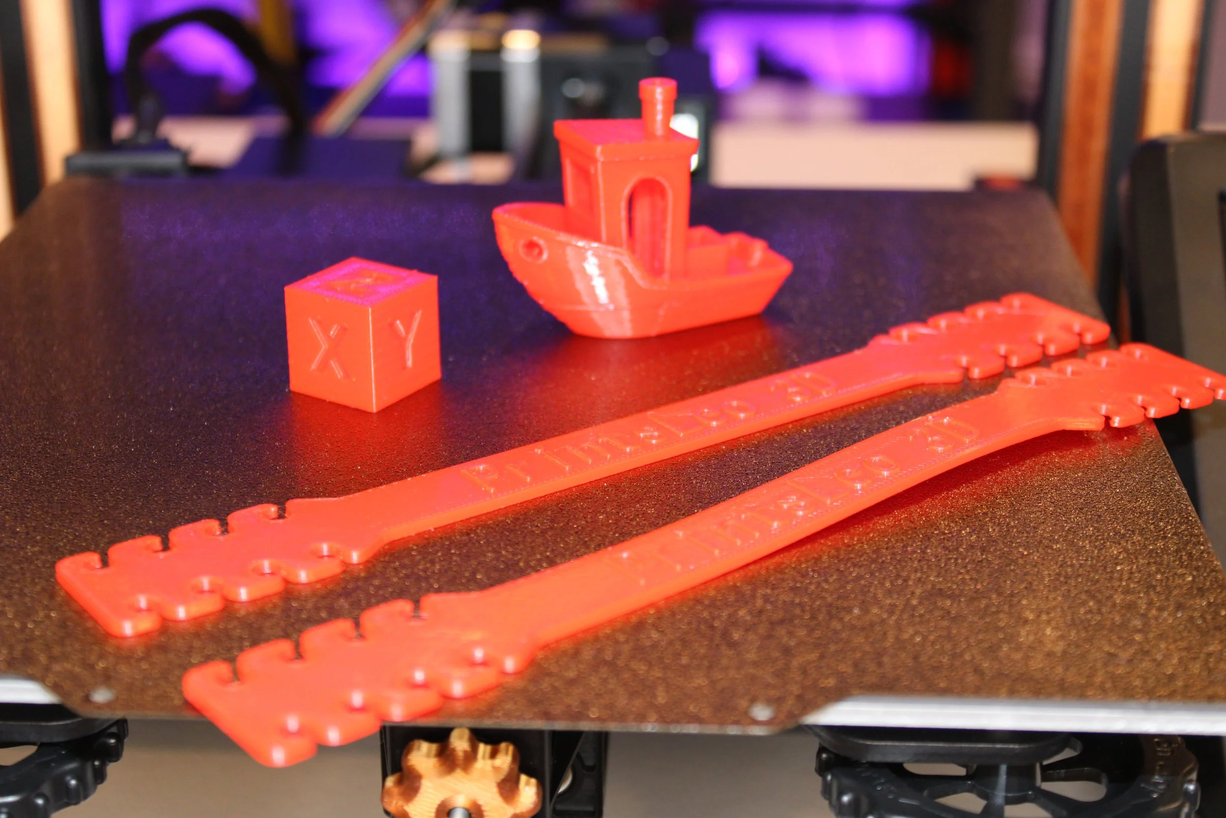
Slicer - Software that converts a virtual model into readable code. The term ‘slicer’ is due to the way in which this software goes about its job. The software will section (or slice) a model into many individual layers, then turn those layers into commands, known as G-code. That G-code is then given to a 3d printer to interpret and produce a finished model. Here’s an introduction video I made to one such slicer, CURA.
Slicing - This is the process of turning a 3d virtual model into G-code by sectioning the model individual layers. To accomplish this we use software called a ‘Slicer’.
Bridging - Refers to long extrusion travels that are unsupported. The term ‘bridging’ is suiting because it’s exactly how they appear. The extruded line will start over a supported part of the model, and then travel over thin air with nothing supporting it, until it reaches another part of the model where it is again supported. The area that remains unsupported would be considered a ‘bridge’.
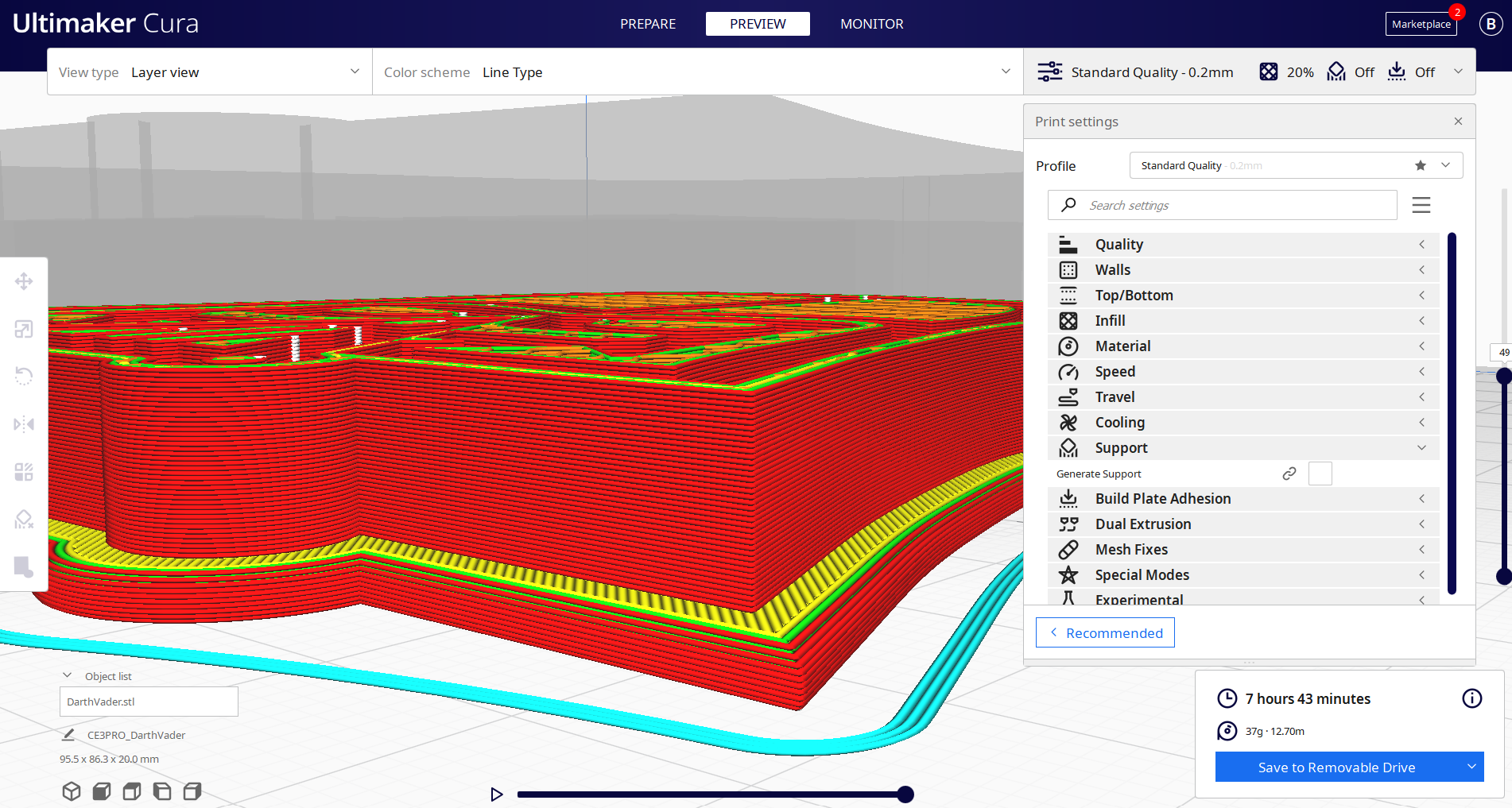
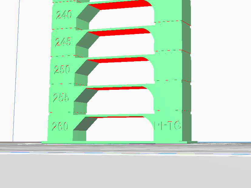
Supports - These are added structures that hold up or ‘support’ parts of a model that would otherwise print in mid air. While supports are meant to ensure the layers above it do not sag, the support itself is intended to have minimal contact with the actual model. [The red portions in the accompanying photo indicate areas that will need supports]
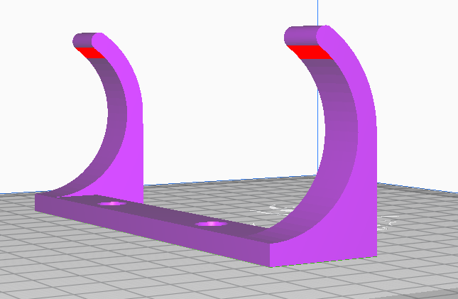
Normal Support
Basic support that is designed in a scaffolding manner. Structure travels in a straight line from the base of the support to just underneath the area needed to be supported.
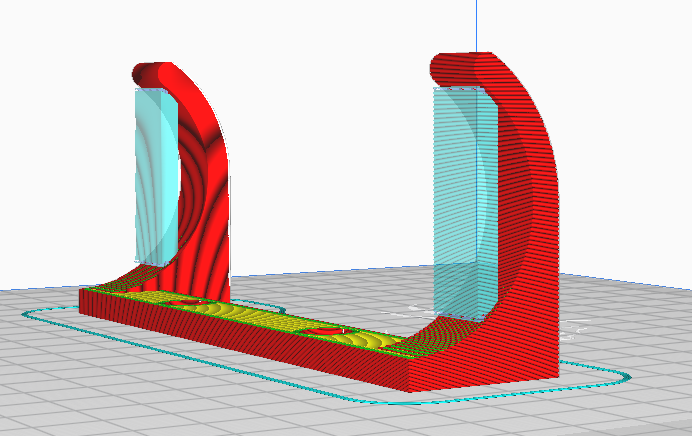
An example of Normal Supports
Tree Support
Advanced support that's design is similar to the branches of a tree. The Supports can originate at a point that is not directly below the area to be supported, allowing these supports to reach - or branch - over sections of your model and support otherwise unsupportable areas.
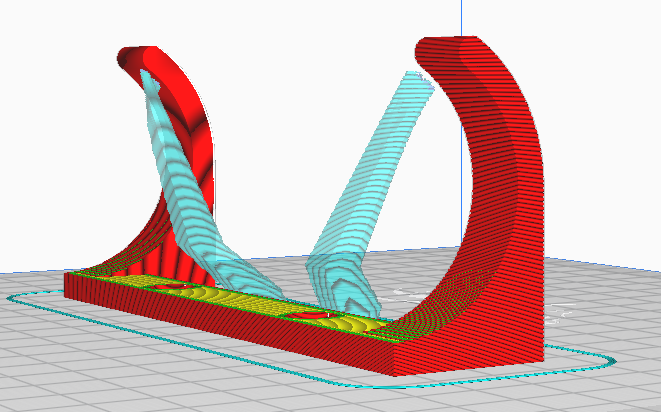
An example of Tree Supports

Eccentric Nuts - The adjustable portions of certain roller wheels that either increase or decrease the wheel tension along the frame. Proper calibration is important to make sure the axes are all moving uniformly.
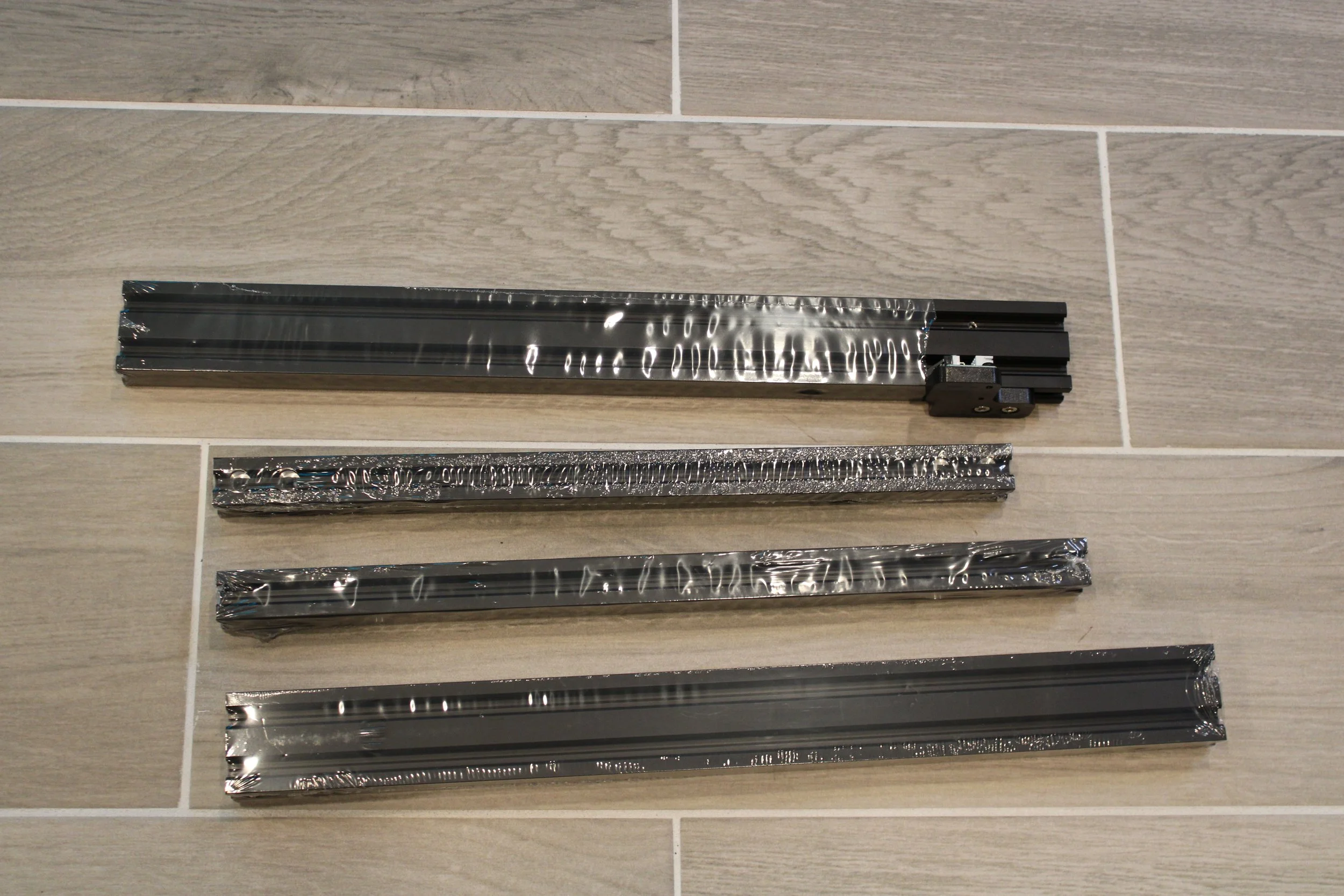
Aluminum extrusion - The metal pieces that makes up the body(frame) of our 3d printer. The aluminum that makes up the frame is heated to an extremely high temperature and then forced into a die that squeezes and cuts it into the desired shape, this process is called ‘extrusion’ and thus the resulting metal profile is referred to as ‘aluminum extrusion’. Aluminum extrusion can also be referred to by it’s profile size, such as 2020 or 2040.
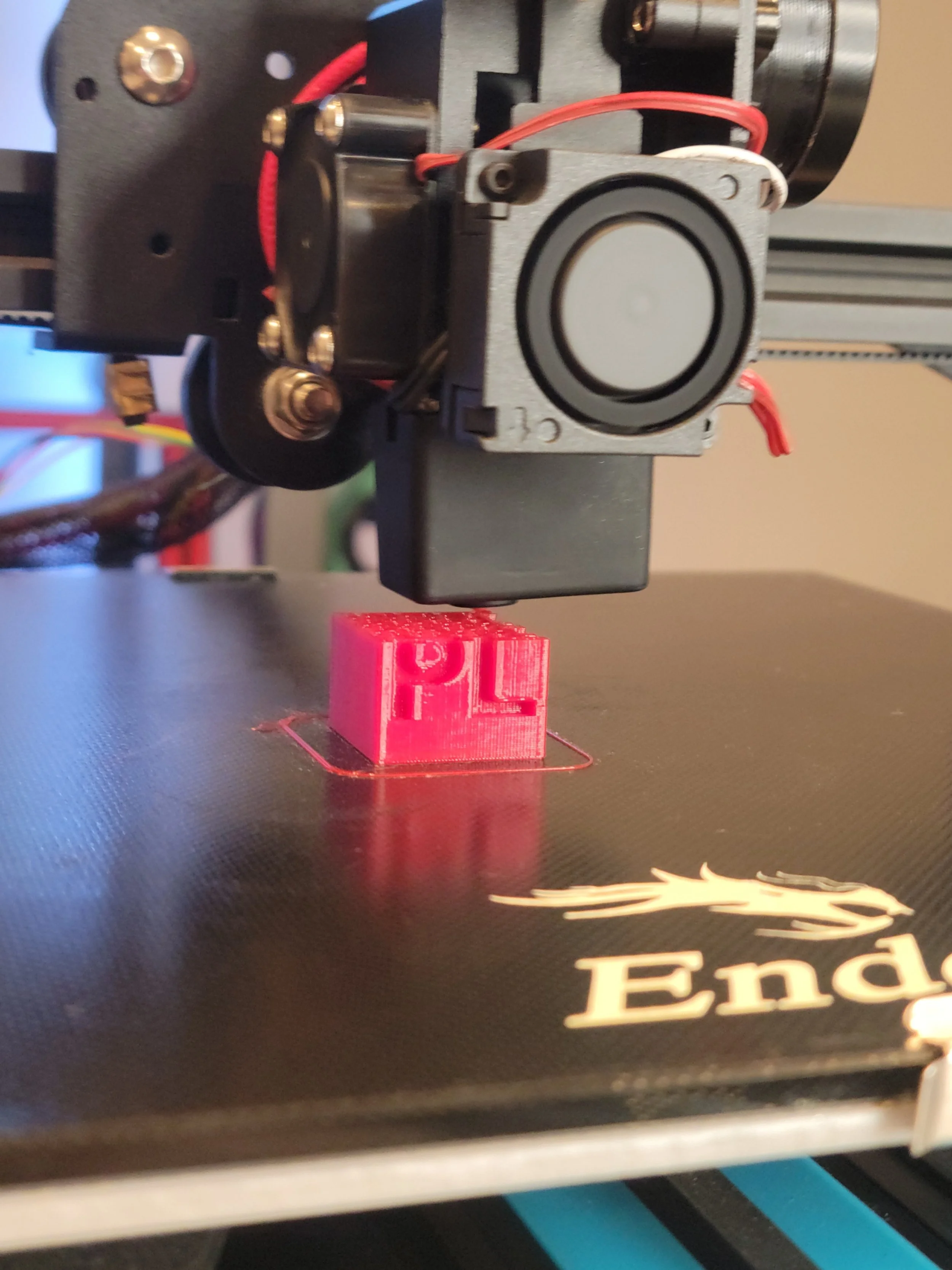
Extrusion - When referring to 3d printers, is the process by which filament is heated, melted, and forced out of the nozzle, onto either the print bed or other layers of a print, that will eventually result in a finished model. This is the process by which prints are created when referring to an FFF/FDM 3d printer.
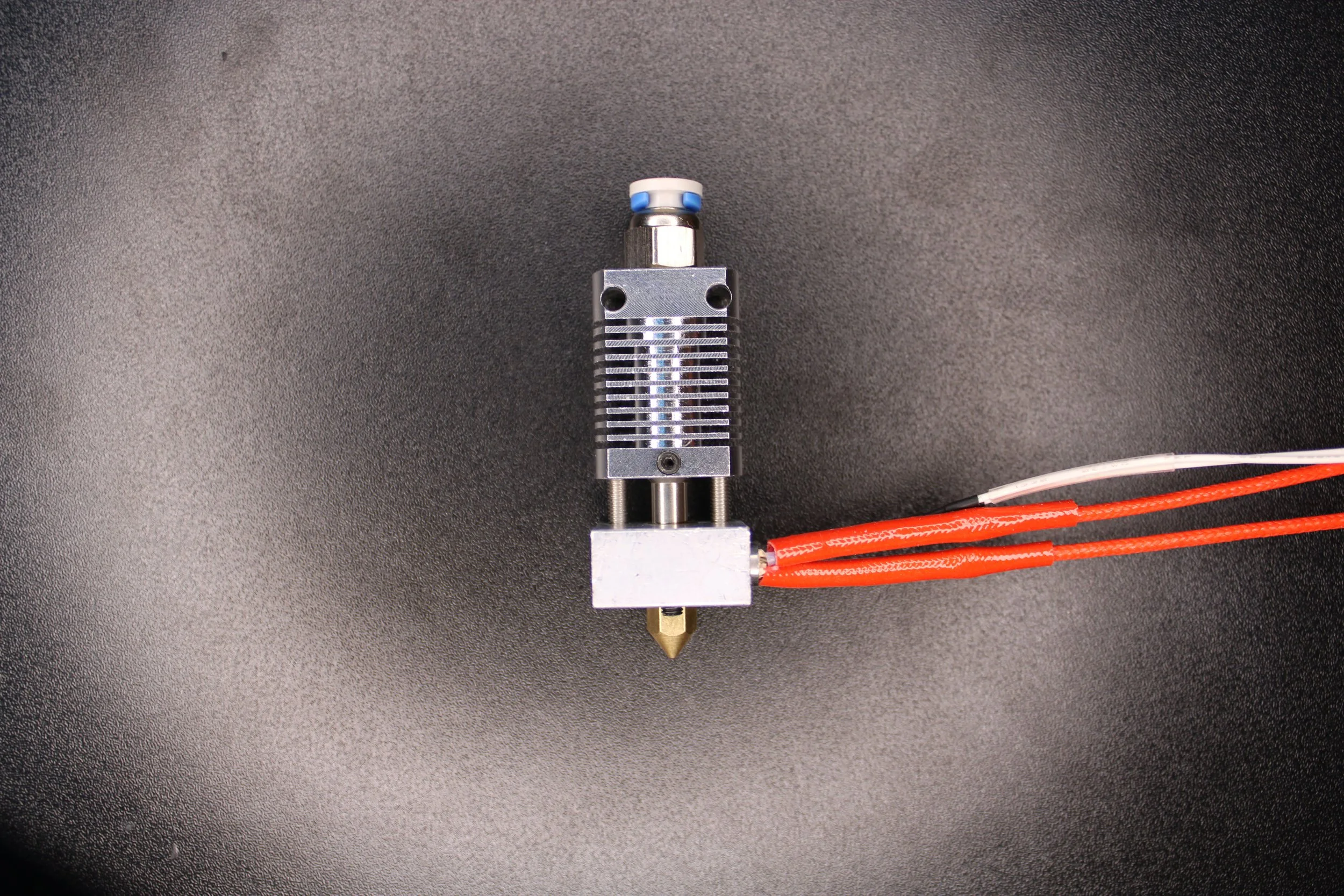
Hot end - This is the heated portion of the Extruder (extruding system), where filament is melted and extruded. It has several components that work in concert to make this operate consistently.
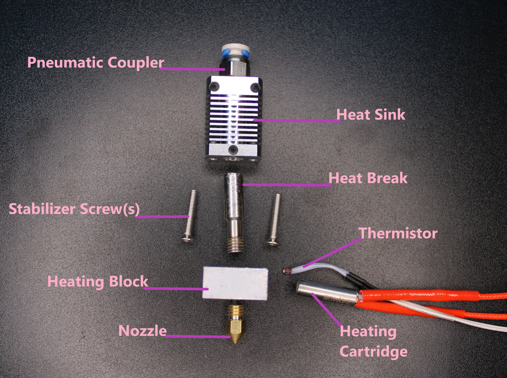
An exploded view of the MK8 hot end
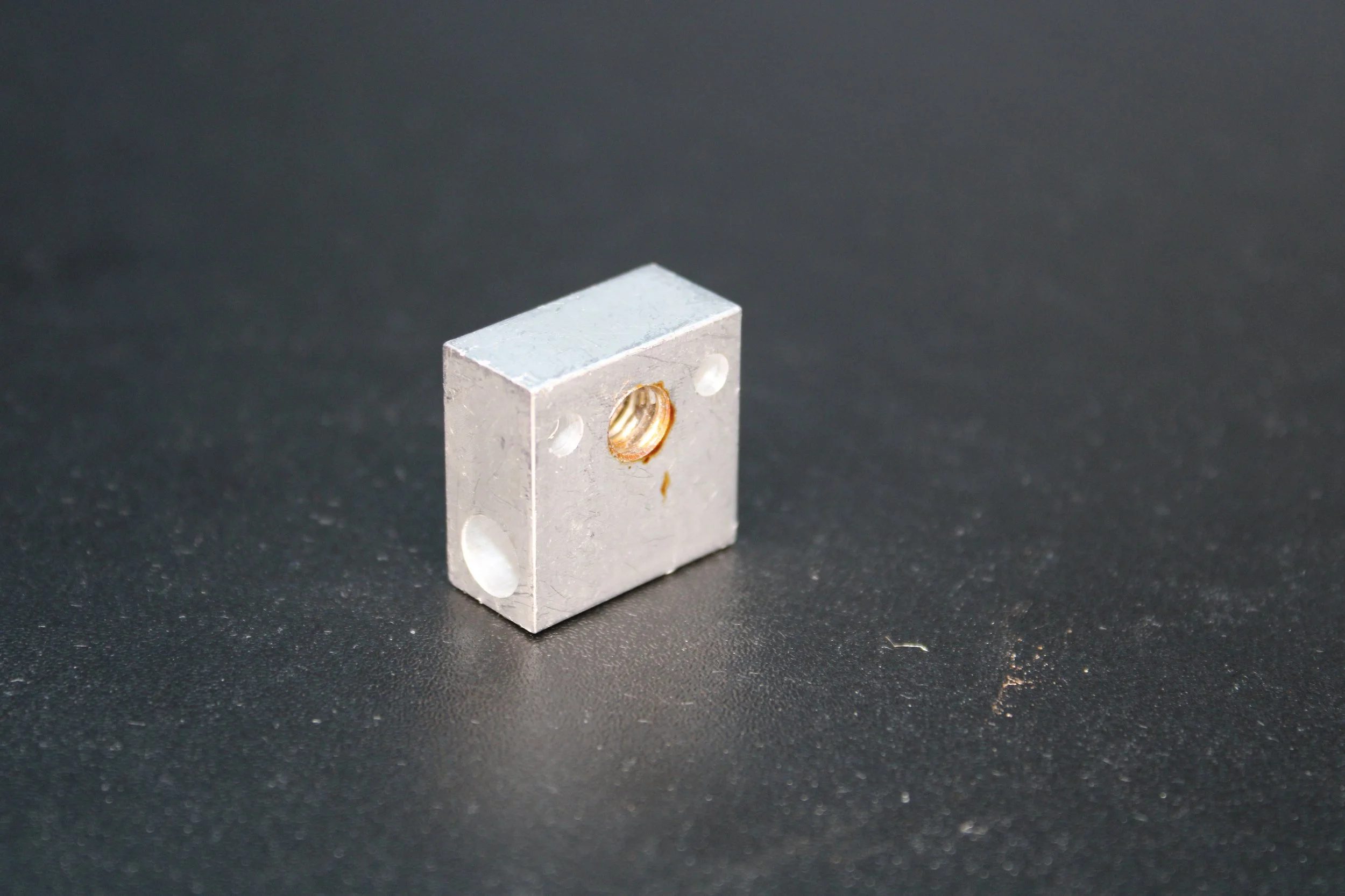
Heating Block - A metal block (usually aluminum) that acts as a medium for the transfer of thermal energy. A heating cartridge within the block provides heat, that heat is transferred to the nozzle which creates a melting chamber for filament. The thermistor, heating cartridge, nozzle, and heat break all reside within the heating block. A silicone sock is used to cover the heating block.
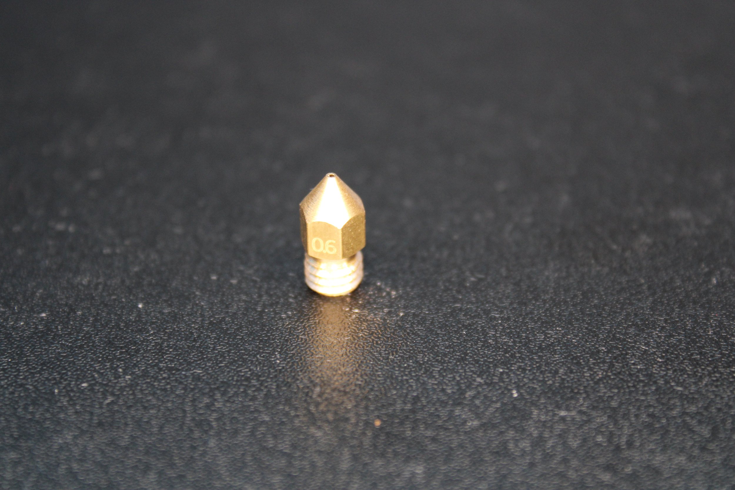
Nozzle - Filament is extruded from the nozzle tip and deposited onto the build plate or a previous layer of material. Nozzles have two different bore sizes, the entrance size and exit size. Generally when referring to a nozzle it is done so by the exit bore size. Most printers come stock with a 0.4mm nozzle. This number is referring to the diameter of the exit bore. The entrance size, where the filament first enters the nozzle, should match the filament you’re using, either 1.75mm or 2.85mm with the former being the most common size. Material is another distinguishing characteristic of a nozzle, where Brass is the de facto norm(due to it’s high thermal conductivity, ease of machining, and low cost). Stainless steel, hardened steel, and even copper plated nozzles are some other options which offer their own pros and cons. Finally length is another quality to the nozzle. The length of the most common nozzles is usually around 12mm, however the length of some nozzles can reach 21mm. These longer nozzles are referred to as ‘Volcano’ nozzles (after the brand name Volcano hot end that uses these). The longer nozzle allows faster printing speeds due to the increased melting zone.

Brass - great conductor of heat, low cost, easy to machine//damaged easily use caution with abrasive filaments,
Stainless Steel - fine conductor of heat, high corrosive resistance, non toxic,
Hardended Steel -
Copper Plated -
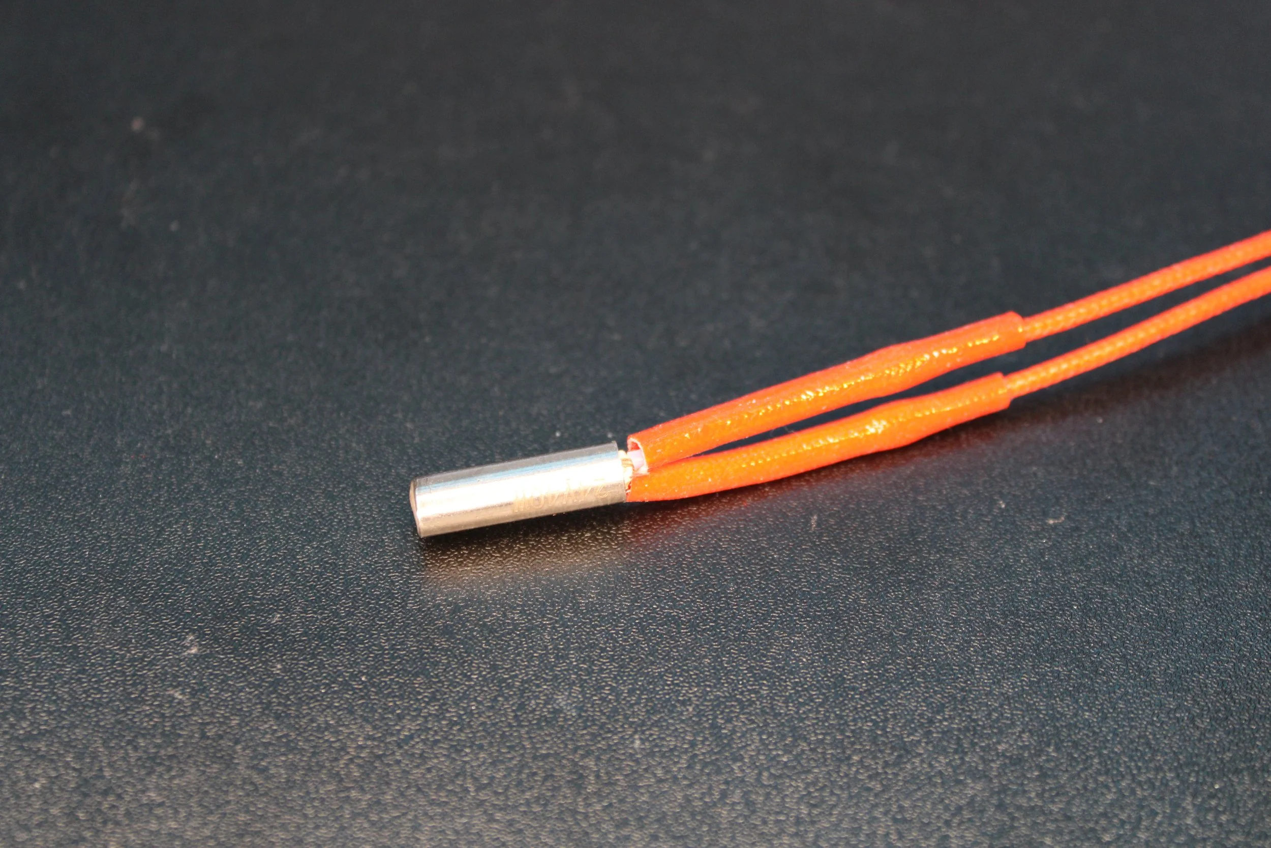
Heating Cartridge - A heating element that is inserted into the heating block which converts electric current into heat. The heat transfers to the heating block, and then ultimately, to the nozzle.
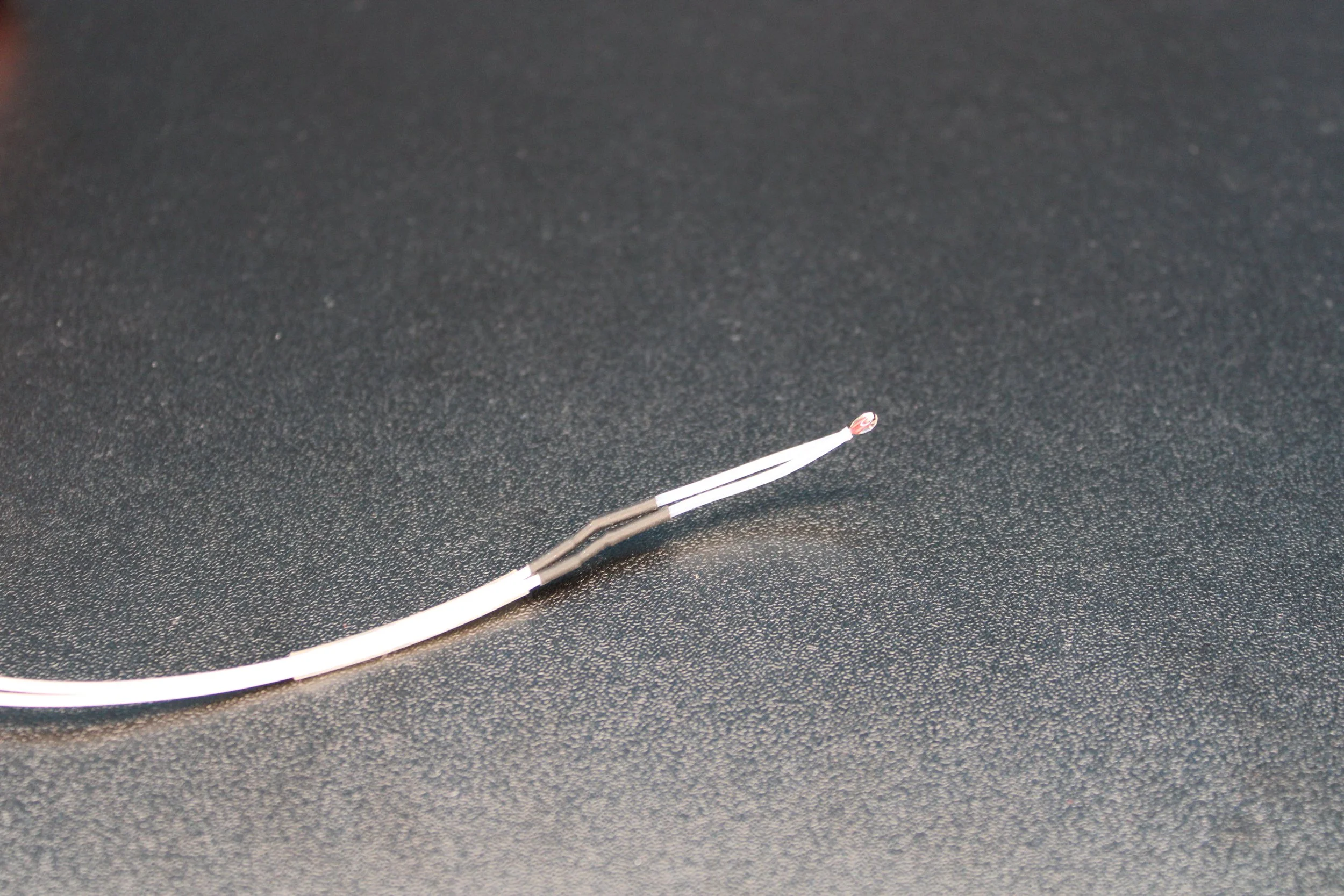
Thermistor - A sensor that is inserted into the heating block of the hot end. It’s function is to send the current temperature back to the mainboard of the 3D printer. As the temperature rises the resistance in the thermistor changes, this information is fed back to the 3D printer and interpreted.
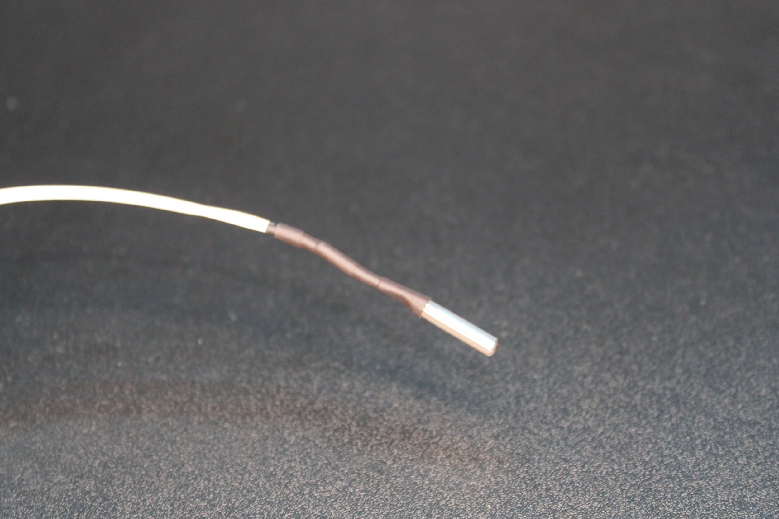
An Example of a cartridge thermistor, something you would see in a ‘Volcano’ style hot end system.

A bi-metal heatbreak, made from Titanium and Copper
Heat Break - This metal chamber is meant to break the travel of heat within the hot end, it separates the ‘cold zone’ of the hot-end from the ‘melting zone’. This is the hot end’s initial portion of heat dissipation and first line of defense against heat creep. Stock components are usually stainless steel which provides smooth filament travel and good thermal conductivity. Aftermarket units can be made from titanium, which is a stronger material and promotes less heat transfer, or a bi-metal combination of a titanium interior and copper exterior, which enhances heat dissipation.
Some heat breaks allow the PTFE tube to pass through it and into the melting zone. This is dangerous, as the PTFE tube will be heated along with your filament, and at temperatures near 230c can offgas harmful chemicals. Other heat breaks separate the PTFE tubing from the melting zone entirely, a hot end that does this is considered ‘ALL METAL’ (a term that has nothing to do with material composition).


Heat Sink - This is the part located farthest from the heat block and thus should be the coldest. Shaped like a vent, or finned vent, it is meant to dissipate any remaining heat that has traveled from the heat break. A portion of the heat break will reside within the heat sink, it’s then the heat sinks job to dissipate any remaining heat that is transferred to it from the heat break. Ideally this part of the hot end is cold, reaching no higher than 40c.

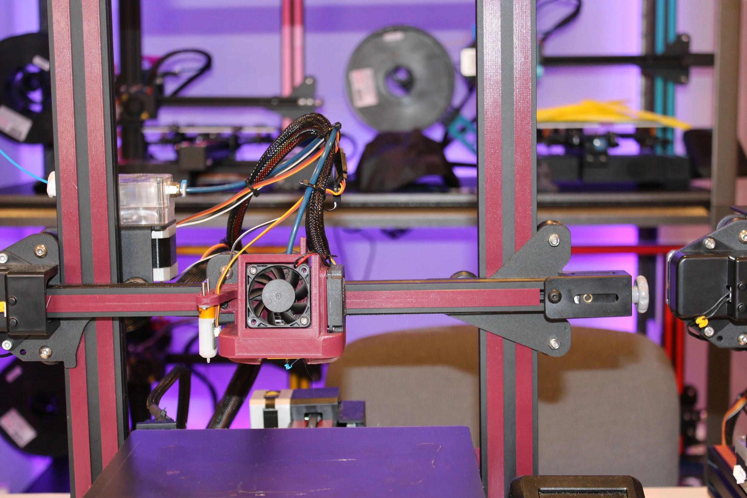
Cooling Fan - The hot end is also getting an assist from the outside, in the form of a cooling fan. A cooling fan will be mounted directly in front of the heat sink, blowing a constant stream of cold air onto the heat sink.
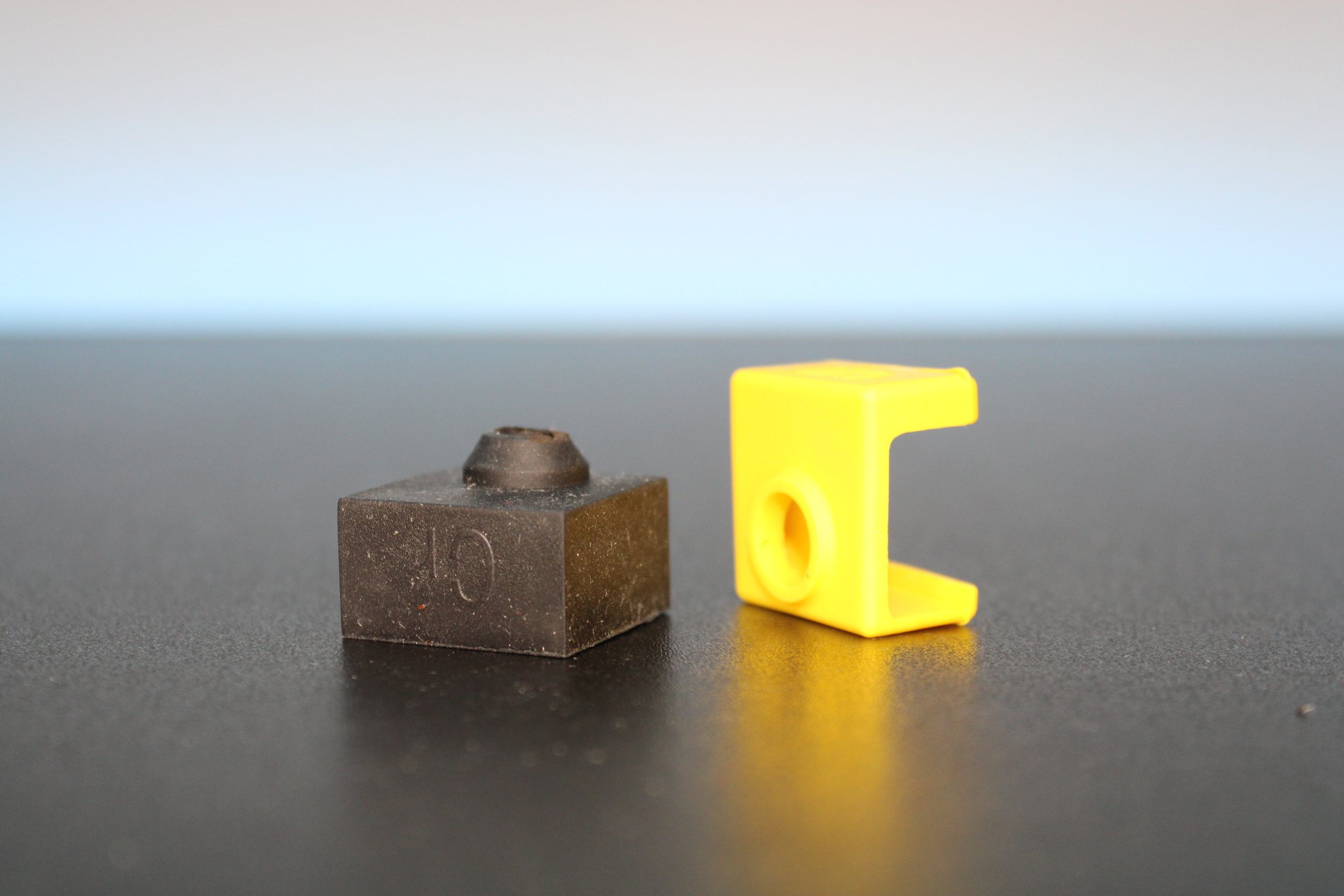
Silicone Sock - It’s job is to insulate the heat block, stopping heat from escaping, which provides a more steady rate of heat. It also protects the user if they get too close to the heat block after/while it is heated, and it stops filament from becoming melted to the block and then dripping onto models while they print.


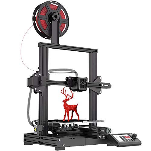
The Voxelab Aquila, an FFF 3D printer
FDM/FFF Printer - FDM (Fused Deposition Modeling) and FFF (Fused Filament Fabrication) both mean the melting of solid filament(thermoplastic) in order to extrude it while in liquid form, layer by layer to create a finished model. When people refer to 3D printing this is likely what they are talking about, as it is the most common and widely used form of 3D printing. The terms FDM and FFF are used interchangeably as they mean the exact same thing, the difference being FDM is a trademarked term by Stratasys(3D printing company), and FFF is an untrademarked term. If there is one feature that separates the two it is a heated chamber that was at some point unique to Stratasys FDM printers. source

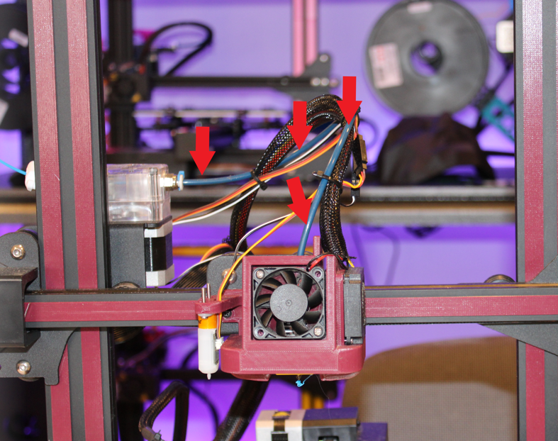
The red arrows show the bowden tube’s travel from the ‘cold end’ to the ‘hot end’
Bowden Tube/PTFE Tube - On some FFF/FDM style printers, the cold end of the extruder is located away from the hot end of the extruder, these types of printers are referred to as Bowden-style printers. In order for the filament to traverse this distance properly it must be maintained and stabilized. Enter the Bowden tube! This is the flexible tubing the filament travels within from the cold end to the hot end. The tubing itself is made of PTFE (teflon) and it’s inner diameter should be slightly bigger than the size of filament being passed within it, as a narrow filament path leads to less movement and better prints. The term Bowden tube is a mechanical term, a bowden tube is used in applications outside of 3d printing and this is the definition: a type of flexible cable used to transmit mechanical force or energy by the movement of an inner cable relative to a hollow outer cable housing. So in our case we have a flexible cable (PTFE tube) and an inner cable (filament). The terms PTFE and Bowden Tube are somewhat interchangeable and most people will refer to them as both.

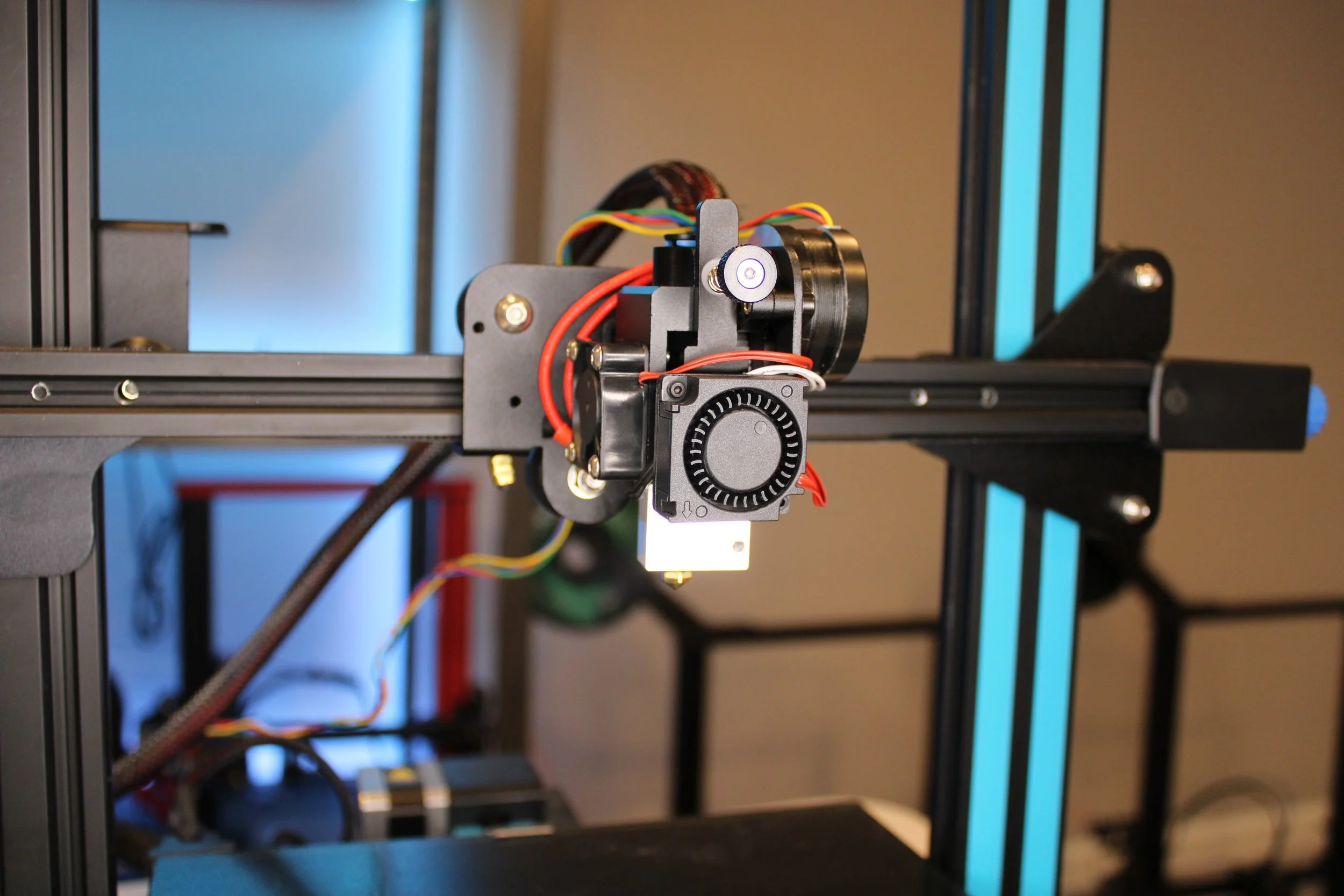
The Haldis Frog Extruder, which attaches the cold end above the hot end.
Direct Extruder(“Direct Drive”) - This type of extruder has the ‘cold end’ seated directly above the ‘hot end’ of the extruder, and pushes the filament straight into the hot end. Retraction distance can be shortened (near 1mm) as the filament is not going to be pulled along a bowden tube. While there is no Bowden tube present in this setup, there is sometimes a small portion of PTFE tubing present between the extruder and hot end to help maintain the filament path. It’s often referred to as a ‘Direct Drive Printer’ which technically is not correct.


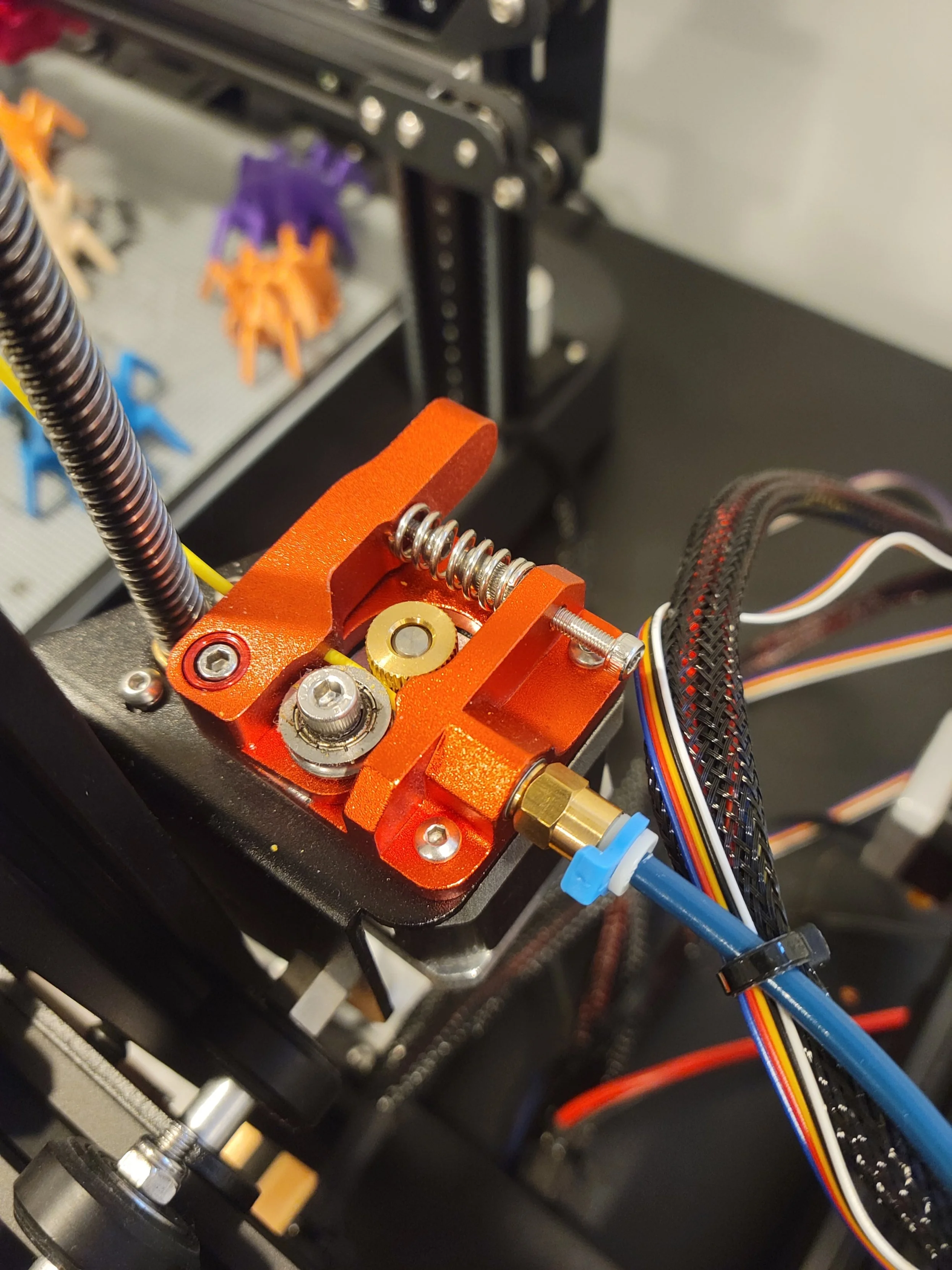
The gold gear that drives the filament is attached directly to the stepper motor.
Direct Drive Extruder - An extruder that has the gnarled gear - that moves filament - attached directly to the extruder stepper motor. That means any movement of the extruder stepper motor is applied straight to the filament. The location of the extruder motor (whether Bowden or Direct) has NO BEARING ON WHETHER A PRINTER IS A DIRECT DRIVE. Common examples of a Bowden Style Direct Drive printer are the Voxelab Aquila and Creality Ender 3.

A BMG clone extruder
Geared Extruder - This extruder employs a transmission gear ratio, as the stepper motor is moving a large gear that then applies rotational force to either one, or two, gnarled gears that grab and move the filament. This type of extruder often requires a larger E-step number, usually somewhere in the 400 steps/mm range. A common example is the BondTech BMG extruder, or one of it’s many clones.


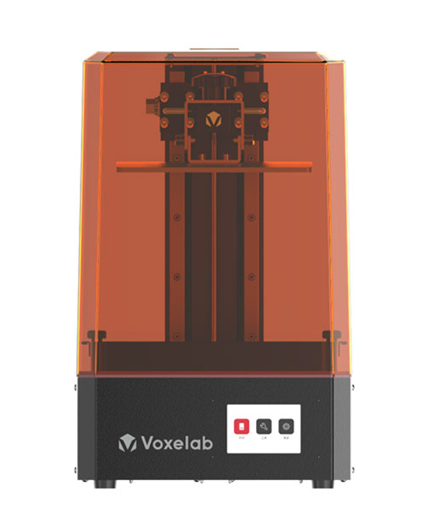
The Voxelab Proxima
SLA/DLP Printer - Both fall under the category of Vat Polymerization printing which is the process of using a light source to turn liquid resin, that is residing in a vat, into a solid model layer by layer. SLA (Stereolithography) and DLP(Digital Light Processing) both turn liquid resin into a solid model by exposing it to a light source, the difference being, in SLA printers, the light source is a Laser, while in DLP printers, the light source is a Projector.
Inherently these two processes have minor differences. Because the distance between the projector and the resin vat needs to be minimal in order to create higher resolution, the build volume for DLP printers will, in general, be smaller than that of SLA printers. The laser present in SLA printers offers the same resolution regardless of distance from the resin vat, and thus can offer a wider build volume and still use a single laser (which will keep the cost down).
DLP printers are inherently faster though, as they are able to flash and cure an entire layer at once, while the laser in SLA printers must trace the layer image from start to finish. The difference in light source also has an effect on the final model. A DLP’s projector light works in Voxels (think of square pixels) and in order to create curved objects must stack several voxels together. Much like pixel art, complicated images can be produced however under scrutiny the sharp edges and jagged curves will be seen. SLA printer’s laser is capable of making curved movements and offers a more ‘accurate’ representation of the desired model.